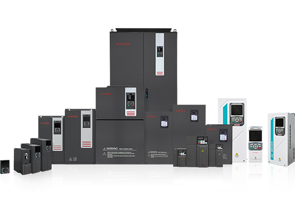


สรุปผลิตภัณฑ์
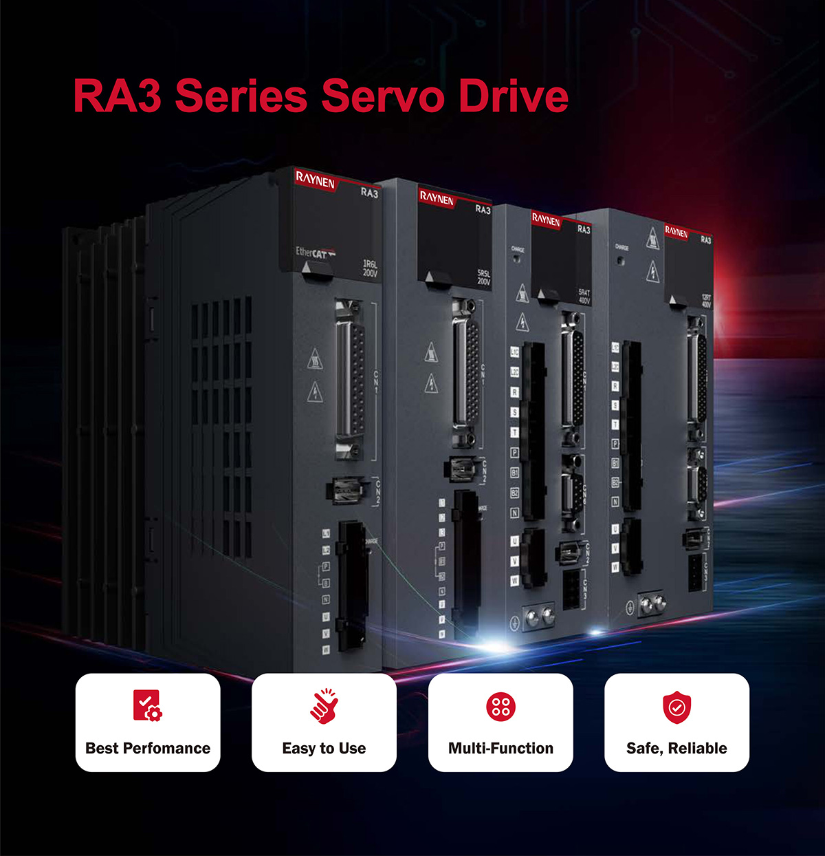
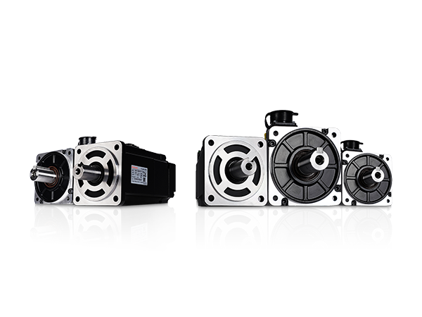
| ช่วงกำลังตั้งแต่ 100W ถึง 7.5KW รองรับพัลส์, อนาล็อก, EtherCAT และ CANopen | |
| ประสิทธิภาพดีเยี่ยม ความถี่ตอบสนองความเร็วสูงสุด 3.0kHz | ตำแหน่งที่แม่นยำ ความเร็วระลอก ±lrpm, แรงบิดกระเพื่อม 0.5% |
| มัลติฟังก์ชั่น STO, วงปิดทั้งหมด, I0 ความเร็วสูง, ระบบป้องกันการสั่นสะเทือน, ตัวกรองรอยบาก, การกลับบ้าน | การซิงโครไนซ์สูงเป็นพิเศษ ความผันผวนของสัญญาณหลายโหนดภายใน 20ns, วงกลมการซิงโครไนซ์สูงถึง 250us |
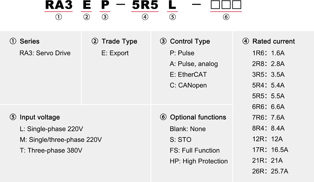
ศัพท์เฉพาะรุ่น
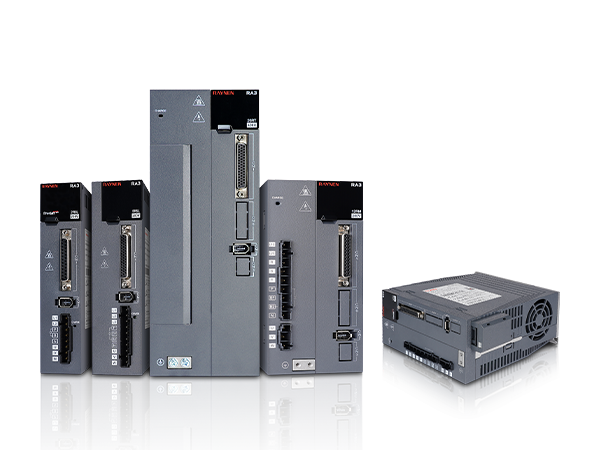
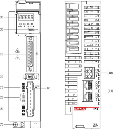
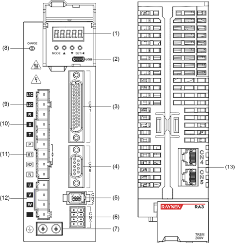
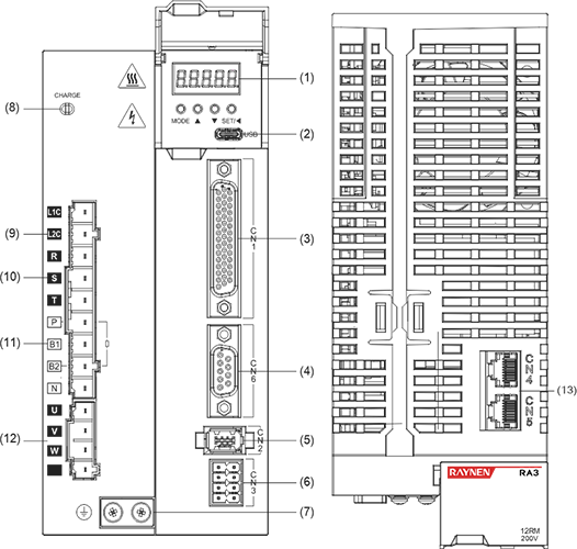
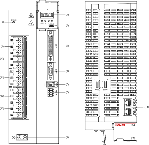
Port Definition
| | | | | | |||||
| Size A | Size B | Size C | Size D | Size E | |||||
| No. | Name | No. | Name | No. | Name | No. | Name | No. | Name |
| 1 | Digital tube display | 1 | Digital tube display | 1 | Digital tube display | 1 | Digital tube display | 1 | Digital tube display |
| 2 | USB | 2 | USB | 2 | USB | 2 | USB | 2 | USB |
| 3 | CN1 | 3 | CN1 | 3 | CN1 | 3 | CN1 | 3 | CN1 |
| Fully closed loop encoder connector | Fully closed loop encoder connector | 4 | CN6 | 4 | CN6 | 4 | CN6 | ||
| 4 | CN2 | 4 | CN2 | 5 | CN2 | 5 | CN2 | 5 | CN2 |
| 5 | L1、L2 | 5 | L1、L2、L3 | 6 | CN3 | 6 | CN3 | 6 | CN3 |
| 6 | P、B | 6 | P、B1、B2 | 7 | Ground screw | 7 | Ground screw | 7 | Ground screw |
| P、N | P、N | 8 | CHARGE | 8 | CHARGE | 8 | CHARGE | ||
| 7 | U、V、W | 7 | U、V、W | 9 | L1C、L2C | 9 | L1C、L2C | 9 | L1C、L2C |
| 8 | Ground screw | 8 | Ground screw | 10 | R、S、T | 10 | R、S、T | 10 | R、S、T |
| 9 | CHARGE | 9 | CHARGE | 11 | P、B1、B2 | 11 | P、B1、B2 | 11 | P、B1、B2 |
| 10 | CN3 | 10 | CN3 | P、N | P、N | 12 | P、N1、N2 | ||
| 11 | CN4/CN5 | 11 | CN4/CN5 | 12 | U、V、W、PE | 12 | U、V、W、PE | N1、N2 | |
| | | | | 13 | CN4/CN5 | 13 | CN4/CN5 | 13 | U、V、W |
| | | | | | | | | 14 | CN4/CN5 |
| Description: ① Digital tube display: 5-digit 8-segment LED digital tube ②USB: USB Type-C interface, connected to PC ③CN1 (interface connector): output/input signal connection port, connected to programmable controller (PLC) or control I/O ④Fully closed-loop encoder connector: fully closed-loop interface, connected to external second encoder, '-FS' model supports this function ⑤CN2 (encoder connector): encoder interface, connected to the encoder on the servo motor ⑥L1, L2, L3 (main power input terminals): main circuit power supply, single-phase power supply is connected between L1 and L2 (200~240VAC, 50/60Hz power supply) ⑦L1C, L2C (control power input electronics): control circuit power supply, connected to single-phase power supply (200~240VAC or 380~440VAC, 50/60Hz power supply according to the model) ⑧R, S, T (main power input terminals ): Main circuit power supply, connect to three-phase power supply (200~240VAC or 380~440VAC, 50/60Hz power supply according to the model) ⑨P, B (external braking resistor connection terminal): use external braking resistor ⑩P, B1, B2 (external braking resistor connection terminal): use external braking resistor (remove the shorting piece between P and B1, connect to both ends of P and B2) ⑪P, N (N1, N2) (servo bus terminal): do not remove the shorting piece between N1 and N2, connect between P and N (N1) for multiple servos to share the DC bus ⑫N1, N2: connect external DC reactor (remove the shorting piece), short-circuit when not in use ⑬U, V, W, PE (servo motor connection terminal): servo drive output, connected to the motor power connector (U, V, W, PE) ⑭ Grounding screw: Connect to the power ground and motor ground ⑮CHARGE (bus voltage indicator): power indicator ⑰CN3 (connector for safety function): STO interface, only '-S/FS' models support this function ⑱CN4/CN5 (communication terminal): 485 communication port, EtherCAT high-speed communication port, CAN communication port | |||||||||

Electrical specifications
| Single-phase / three-phase 220V drive electrical specifications | ||||||||||||
| Item | Size A | Size B | Size C | Size D | Size C | Size D | Size E | |||||
| Model | 1R6L | 2R8L | 5R5L | 5R6L | 7R6M* | 12RM* | 7R6M | 12RM | 18RN | 22RN | 27RN | |
| Power supply capacity [kVA] | 0.5 | 1 | 1.7 | 2 | 2.3 | 4.2 | 2.3 | 4.2 | 6.9 | 8.4 | 10.3 | |
| Continuous output current [Arms] | 1.6 | 2.8 | 5.5 | 6.6 | 7.6 | 12 | 7.6 | 12 | 18 | 22 | 27 | |
| Instantaneous maximum output current [Arms] | 5.9 | 10.1 | 16.9 | 17 | 23 | 32 | 233 | 32 | 45 | 55 | 67.5 | |
| Main circuit | Continuous input current [Arms] | 2.3 | 4 | 7.9 | 9.4 | 10.5 | 19.1 | 5.1 | 8.1 | 15 | 18 | 22 |
| Main circuit power supply | Single phase 200~240VAC, -10%~ 10%, 50/60Hz | Three-phase 200~240VAC, -10%~ 10%, 50/60Hz | ||||||||||
| Control loop | Control circuit power supply | Busbar power supply, shared power supply input and rectification | Single phase 200~240VAC, -10%~ 10%, 50/60Hz | |||||||||
| Power loss | Main circuit power loss [W] | 30.5 | 41 | 60.8 | 63 | 42.9 | 83.3 | 42.9 | 83.3 | 170 | 208 | 278 |
| Control circuit power loss [W] | 22 | 25 | 22 | 25 | 27 | 27 | 27 | |||||
| Braking resistor | Brake resistor function | No built-in support | Standard built-in | |||||||||
| Resistance value [Ω] | - | - | 50 | 50 | 25 | 25 | 25 | 25 | 20 | 20 | 20 | |
| Capacity [W] | - | - | 50 | 50 | 80 | 80 | 80 | 80 | 100 | 100 | 100 | |
| External minimum allowable resistance value [Ω] | 50 | 45 | 40 | 40 | 20 | 15 | 20 | 15 | 15 | 15 | 15 | |
| Maximum braking energy that the capacitor can absorb [J] | 10.03 | 20.06 | 28.57 | 28.57 | 41.34 | 60.8 | 41.34 | 60.8 | 99.7 | 121.6 | 121.6 | |
| Cooling method | Natural cooling | Air Cooling | ||||||||||
| Overvoltage level | OVC III | |||||||||||
*7R6M and 12RM recommend three-phase 220V input for better performance
| Three-phase 380V drive electrical specifications | ||||||||
| Item | Size C | Size D | Size E | |||||
| Model | 3R5T | 5R4T | 8R4T | 12RT | 17RT | 21RT | 26RT | |
| Power supply capacity [kVA] | 2.3 | 3.5 | 4.5 | 6.2 | 8.1 | 11 | 14.5 | |
| Continuous output current [Arms] | 3.5 | 5.4 | 8.4 | 12 | 16.5 | 21 | 25.7 | |
| Instantaneous maximum output current [Arms] | 11 | 14 | 20 | 29.75 | 41.25 | 52.12 | 64.25 | |
| Main circuit | Continuous input current [Arms] | 3.4 | 4.5 | 6.6 | 9.3 | 12 | 16 | 21 |
| Main circuit power supply | Three-phase 380~440VAC, -10%~ 10%, 50/60Hz | |||||||
| Control loop | Control circuit power supply | Single phase 380~440VAC, -10%~ 10%, 50/60Hz | ||||||
| Power loss | Main circuit power loss [W] | 34.4 | 70.9 | 95 | 155 | 238 | 275 | 336 |
| Control circuit power loss [W] | 22 | 22 | 25 | 25 | 27 | 27 | 27 | |
| Braking resistor | Brake resistor function | Standard built-in | ||||||
| Resistance value [Ω] | 100 | 100 | 50 | 50 | 35 | 35 | 35 | |
| Capacity [W] | 80 | 80 | 80 | 80 | 100 | 100 | 100 | |
| External minimum allowable resistance value [Ω] | 80 | 60 | 45 | 40 | 35 | 25 | 25 | |
| Maximum braking energy that the capacitor can absorb [J] | 33.2 | 40.33 | 59.3 | 59.3 | 97.26 | 118.61 | 118.61 | |
| Cooling method | Air Cooling | |||||||
| Overvoltage level | OVC III | |||||||
Product size
| Size A | |||||||||||||||||
| |
| ||||||||||||||||
| Size B | |||||||||||||||||
| |
| ||||||||||||||||
| Size C | |||||||||||||||||
| |
| ||||||||||||||||
| Size D | |||||||||||||||||
| |
| ||||||||||||||||
| Size E | |||||||||||||||||
| |
| ||||||||||||||||


Wiring Diagram
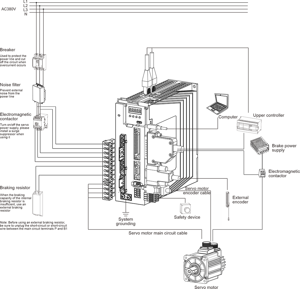
Note: The figure shows the wiring diagram of the RA3 series three-phase 380V Size C/D. For wiring diagrams of other models, please contact customer service.
-1.5(2.2)กิโลวัตต์ วีเอฟดี")
-7.5(11)กิโลวัตต์ วีเอฟดี")
-15(18)กิโลวัตต์ วีเอฟดี")